Tel: 137-2421-1742 E-mail: paul@rdbuy.cn
ICP备案证书号:粤ICP备12082730号-1
共执行 70 个查询,用时 0.021325 秒,在线 826 人,Gzip 已启用,占用内存 2.690 MB
Powered by ECShop v4.0.1


![CMR3100-D01 Murata消费级三轴MEMS陀螺仪[停产]](images/201212/thumb_img/385_thumb_G_1356334509838.jpg)


ADXL345测试笔记
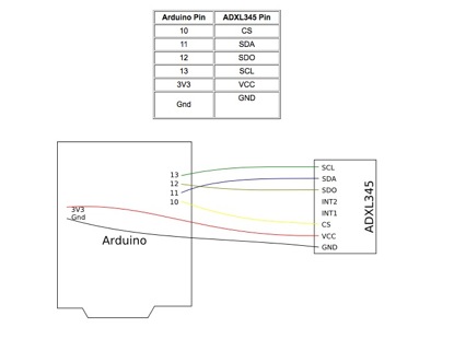
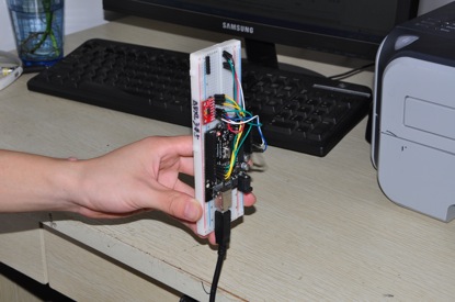
1、与测试装置连接:
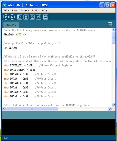
2、测试代码:
//Add the SPI library so we can communicate with the ADXL345 sensor
#include <SPI.h>
//Assign the Chip Select signal to pin 10.
int CS=10;
//This is a list of some of the registers available on the ADXL345.
//To learn more about these and the rest of the registers on the ADXL345, read the datasheet!
char POWER_CTL = 0x2D; //Power Control Register
char DATA_FORMAT = 0x31;
char DATAX0 = 0x32; //X-Axis Data 0
char DATAX1 = 0x33; //X-Axis Data 1
char DATAY0 = 0x34; //Y-Axis Data 0
char DATAY1 = 0x35; //Y-Axis Data 1
char DATAZ0 = 0x36; //Z-Axis Data 0
char DATAZ1 = 0x37; //Z-Axis Data 1
//This buffer will hold values read from the ADXL345 registers.
char values[10];
//These variables will be used to hold the x,y and z axis accelerometer values.
int x,y,z;
void setup(){
//Initiate an SPI communication instance.
SPI.begin();
//Configure the SPI connection for the ADXL345.
SPI.setDataMode(SPI_MODE3);
//Create a serial connection to display the data on the terminal.
Serial.begin(9600);
//Set up the Chip Select pin to be an output from the Arduino.
pinMode(CS, OUTPUT);
//Before communication starts, the Chip Select pin needs to be set high.
digitalWrite(CS, HIGH);
//Put the ADXL345 into +/- 4G range by writing the value 0x01 to the DATA_FORMAT register.
writeRegister(DATA_FORMAT, 0x01);
//Put the ADXL345 into Measurement Mode by writing 0x08 to the POWER_CTL register.
writeRegister(POWER_CTL, 0x08); //Measurement mode
}
void loop(){
//Reading 6 bytes of data starting at register DATAX0 will retrieve the x,y and z acceleration values from the ADXL345.
//The results of the read operation will get stored to the values[] buffer.
readRegister(DATAX0, 6, values);
//The ADXL345 gives 10-bit acceleration values, but they are stored as bytes (8-bits). To get the full value, two bytes must be combined for each axis.
//The X value is stored in values[0] and values[1].
x = ((int)values[1]<<8)|(int)values[0];
//The Y value is stored in values[2] and values[3].
y = ((int)values[3]<<8)|(int)values[2];
//The Z value is stored in values[4] and values[5].
z = ((int)values[5]<<8)|(int)values[4];
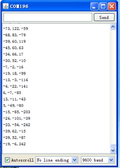
//Print the results to the terminal.
Serial.print(x, DEC);
Serial.print(',');
Serial.print(y, DEC);
Serial.print(',');
Serial.println(z, DEC);
delay(10);
}
//This function will write a value to a register on the ADXL345.
//Parameters:
// char registerAddress - The register to write a value to
// char value - The value to be written to the specified register.
void writeRegister(char registerAddress, char value){
//Set Chip Select pin low to signal the beginning of an SPI packet.
digitalWrite(CS, LOW);
//Transfer the register address over SPI.
SPI.transfer(registerAddress);
//Transfer the desired register value over SPI.
SPI.transfer(value);
//Set the Chip Select pin high to signal the end of an SPI packet.
digitalWrite(CS, HIGH);
}
//This function will read a certain number of registers starting from a specified address and store their values in a buffer.
//Parameters:
// char registerAddress - The register addresse to start the read sequence from.
// int numBytes - The number of registers that should be read.
// char * values - A pointer to a buffer where the results of the operation should be stored.
void readRegister(char registerAddress, int numBytes, char * values){
//Since we're performing a read operation, the most significant bit of the register address should be set.
char address = 0x80 | registerAddress;
//If we're doing a multi-byte read, bit 6 needs to be set as well.
if(numBytes > 1)address = address | 0x40;
//Set the Chip select pin low to start an SPI packet.
digitalWrite(CS, LOW);
//Transfer the starting register address that needs to be read.
SPI.transfer(address);
//Continue to read registers until we've read the number specified, storing the results to the input buffer.
for(int i=0; i<numBytes; i++){
values[i] = SPI.transfer(0x00);
}
//Set the Chips Select pin high to end the SPI packet.
digitalWrite(CS, HIGH);
}
将以上代码复制到arduino IDE,并下载到arduino 控制板中。
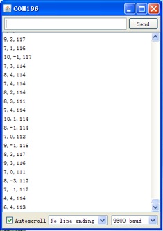
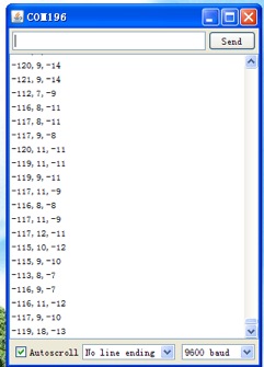
3、 数据的读取与判断:
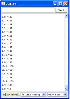
水平放置状态:

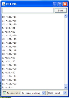
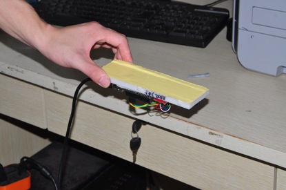
左右翻转90度:
左右翻转90度X轴读书会发生较大变化。
前后翻转90度: 
前后翻转90度Y轴读书发生较大变化。
上下翻转180度:
上下翻转180度Z轴读书发生较大变化。
另外在沿着X轴方向水平用力晃动时,X轴数据发生较大变化,而其它两个轴变化较小:
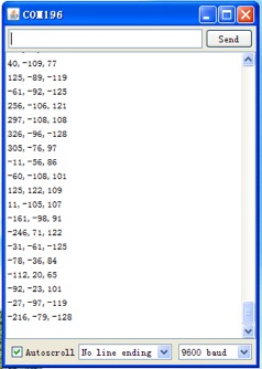
沿着Y轴方向水平用力晃动,Y轴数据发生较大变化,而其它两个轴变化较小:
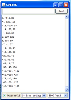
沿着Z轴上下垂直用力晃动,Z轴数据发生较大变化,而其它两个轴变化较小: